Sunday, April 30, 2006

Below Stairs

Caller:" Hello, hello, is this the Revit Help Desk " ?

Help Desk: " Yes, how can we help... "

Caller: " Well, I've got this spiral stair and I need to put a wall under it... and I've got to get this project out the door, like yesterday... "
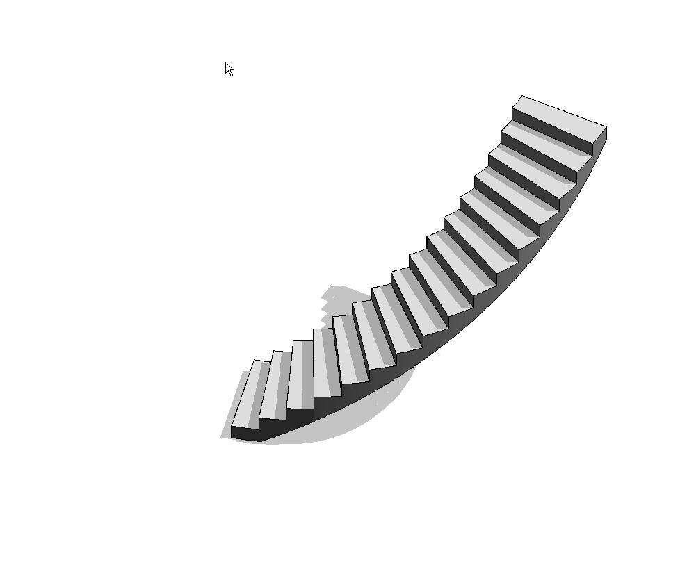


Help Desk: " OK, take a breath, ... Now , firstly you could set up a couple of reference planes each side of the stair, making sure they don't intersect the stair, then name them, then draw detail lines aligned with each stair riser projecting out to each reference plane, then create a new framing elevation using the front named reference plane, checking that the view extents encompass the rear reference plane, then add reference planes where the detail lines intersect both the front and back reference planes ...... "


Caller: "Hey ! I said I need this now ! not next week ! Whadamean create named reference planes and framing elevations ! I can't believe this - there must be a simpler way ! "


Help Desk: ( Calm and patient as always ): " Well yes, but it does involve a work-around... "


Caller: " Great ! I don't care what it involves - just give it to me straight "


Help Desk: " OK, first, select the Ramp tool from the modeling Tab ..."

Caller: " Hey ! I said I wanted a wall, not a *$#@^ Ramp - how long have you been using Revit ? "

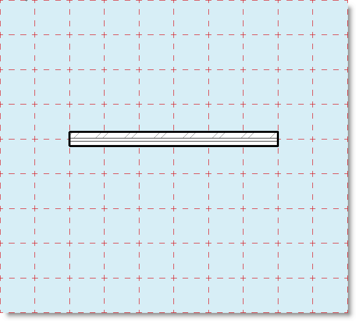
Help Desk: ( Calm and patient , but not as calm and patient.. ): " Yes, I know - this is a work around - trust me. Create a new Ramp type and sketch a ramp -like this... same thickness as your wall "


Caller: " Riiight, .... you sure you know what you're doing here... ? "

Help Desk: " Trust me ...., now, from you stair properties, your Actual riser height is ... ? "

Caller: " 177.8 mm "

Help Desk: " And your Actual tread depth is ... "

Caller: " 250 mm "

Help Desk: " OK, so the Ramp Max Slope Type property ( l/x ) should be 250 / 177.8 = 1.4060742. Enter that in the Type Properties, Other... "

Caller: " Hmmmm, OK .... "

Help Desk: " Now measure from the underside of the stair to the upper level - what do you get ? "

Caller: " Ahhh, 550 mm "

Help Desk: " OK, enter that as the Top Offset with a negative dimension "


Help Desk : " Now finish - Click OK " and check out the 3D View "


Caller: " Wow - thanks - you saved me ! Now, how do I put a door in that wall... ? "

Help Desk: " Ahhhh, .... please hold, I have a another call coming in.... "

Tuesday, April 25, 2006

Two Pick , or not...

Revit Building 9 introduces a new family type, known as two pick families.

There are a couple of new family templates provided for creating these families -

  • Generic Model line based.rft
  • Detail Component line based.rft

Both new families contain a reference line with a length dimension attached to it, labeled with the instance parameter length.

Family geometry is built on this reference line and constrained to it.

The resulting family is placed in the same fashion as a wall - by picking two points.

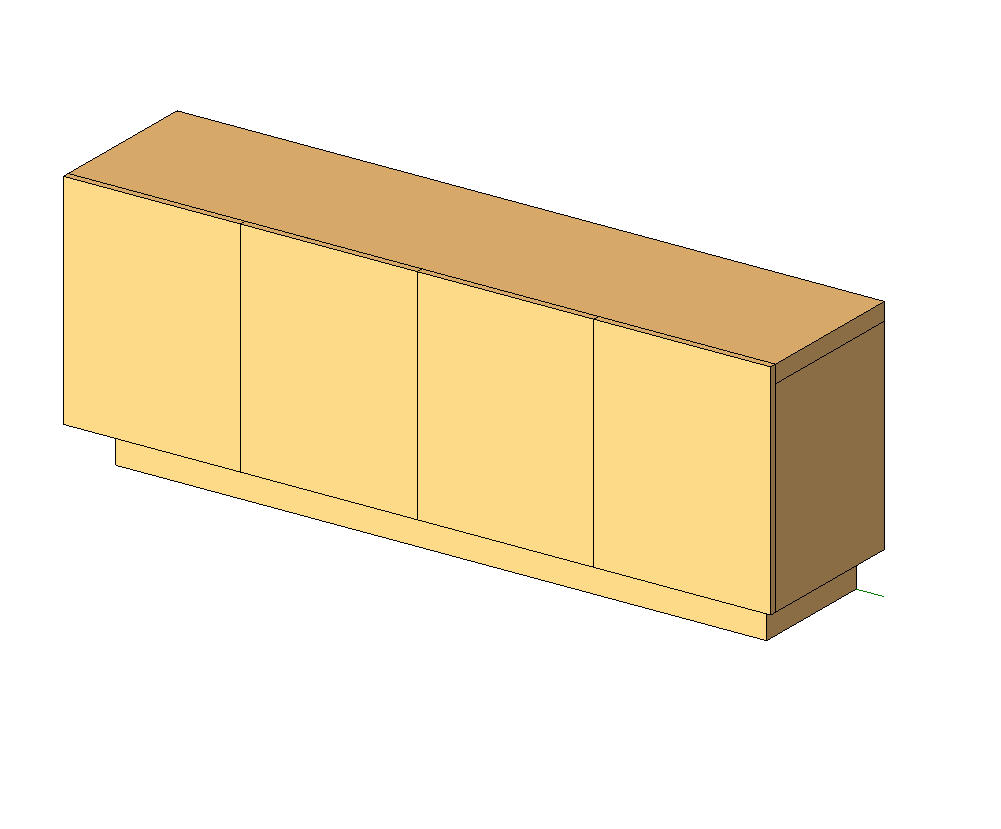
We will proceed to build a Kitchen cabinet family using the Generic Model line based template.

File > New > Family > ( Metric or Imperial ) Generic Model Line Based.rft
We will now construct the carcase for the cabinet.

Add a new Reference Plane and lbel as Carcase Depth - Type parameter.


Soid Form > Solid Extrusion. Sketch the carcase and constrain the sketch to the two side Reference Planes and the rear Reference Line.
Dimension and constrain the carcase thickness ( Keeping it simple for now )


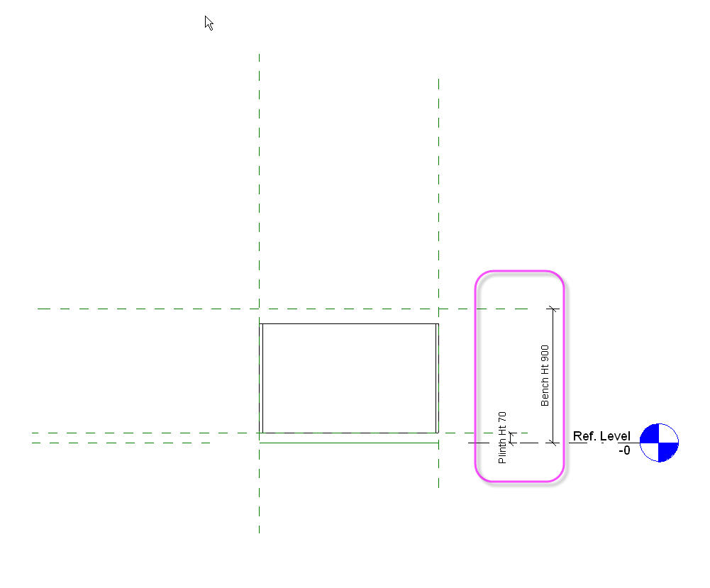
In the front Elevation view, add two new Reference Planes and label them as Bench Height and Plinth Height.
Constrain the carcase to the Plinth Height RP.

Sketch the bench top and the base and constrain to the appropriate Reference Lines.


Add a mid shelf if you wish.

Open a new generic Based family template.

Construct a door panel, with Width and Height parameters ( Thickness can be a parameter or fixed )

Nest this door panel into your 2Pick Cabinet Family.
Constrain to the front RP and to the Left hand ( origin side ) Reference Plane and to the fromt RP.
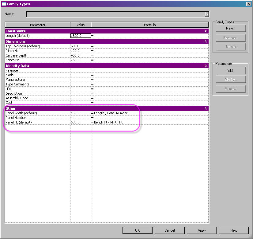
Set up new parameters as follows :-

Set up a new RP and constrain it to the Panel Width.
Assign the Panel Width and Panel Height parameters to the host families equivalent parameters.
Array the nested door panel, first to last, grouped and constrain the origin to the new RP.

Assign the array number to the parameter " Panel Number "
Go to the front elevation view and constrin the top of the first panel to the Bench Top height.

Flex the family to ensure that everything is working properly.
Add a plinth using a sweep.

Now save, then load the family into a project.
You can now place the cabinet with two picks like a wall.


Cool bananas.

In a future article, we'll look at enhancing the functionality of this family by adding voids to cut the end and the plinth for " L " shaped units, etc.


Saturday, February 18, 2006

North By Northwest

Hitchcock's 1959 action film North By Northwest, relied on mistaken identity and contained a great deal of extraneous detail to make a simple plot into one of the director's most loved films.

Today, Revit's Project North and True North also create a deal of confusion and mistaken identity among both new and more experienced users.

Lets look at a common scenario in many offices :-

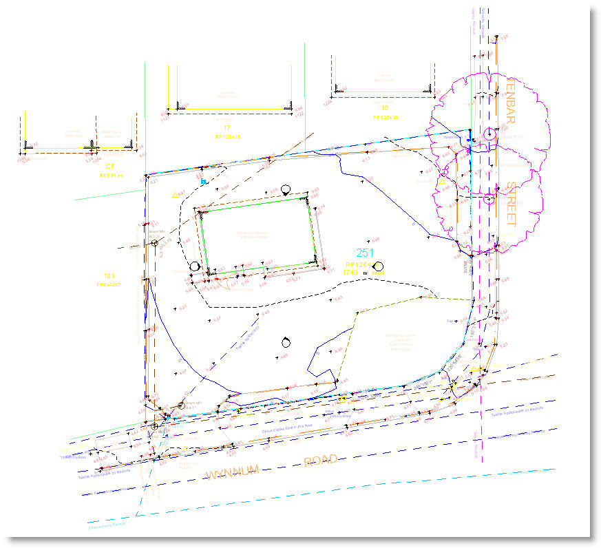
We have a survey dwg from our consultant. We want to use that to create our site boundaries and eventually our topo surface in our Revit file.

The survey drawing is, of course, already orientated to True North.

We import the dwg survey into our project. We import it into the Site Plan view, using Current view and leaving the default orientation set to Project North in the View Properties.


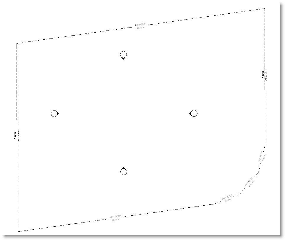
Examining the survey, we determine that the top boundary has a bearing of 82 deg. We want that boundary to be horizontal on our sheet view. Our sheet view will be set to Project North. We will therefore, need to rotate the survey dwg and our property boundaries 8 deg clockwise, to get the correct orientation for Project North.


But first, we need to draw our Revit property lines.

The easy way to do this, is to use Revits query command to identify the layer that contains the boundary line information. Its on layer Boundary_Subject in our case. ( It would be nice if we could isolate it from within the query dialogue, but we can only hide, or delete it )

Under Visibility Graphics, we select the dwg import and turn off all the layers except for Boundary_Subject. We then use the Property line by sketch tool to pick the boundaries. ( remember - hover, tab selects all. )

Turning off our dwg underlay, we can see our Revit property lines. Now we can tag the boundaries using the Tag All Not Tagged feature.


Next, we must rotate the property lines and the dwg to the desired orientation for our sheet views. We do not want to rotate the elevation views tags though.

Turn the dwg back on ( all layers ). Draw a selection box around everything in the Site Plan view, then use the Filter tool to uncheck the Elevation view tags.

Now use the Rotate tool to rotate 8 deg clockwise.


The Site Plan View is now correctly set for Project North ( ie for placing on sheets )

Next, we have to set True North. ( If this is sounding like the plot from an old Hitchcock movie, then I did warn you ! )

It is a relatively straight forward process though.

Rename the Site plan to Site Project North, or similar, so you know which view to use.

Make a duplicate ( with detailing, if you want the dwg visible in this view as well ) of the Site Plan view and rename it Site True North.

Turn off the dwg , for clarity.

Open the View Properties of the duplicated view and change the orientation to True North ( from Project North )

Now, using the Tools menu, Project Position / Orientation, Rotate True North, rotate the project 8 deg anti-clockwise.

You now have a view for each of the desired orientations Project North and True North. The bearings on each property line are correct in both views. The Elevation tags are orientated for the Project North view orientation.

I hope you don't feel like you've just been chased across the face of Mount Rushmore !

But at least now you'll know how to change from North to North West. ( or from Project to True North )

Friday, January 27, 2006

New Revit Blog - In Plain English

Great to see more Revit blogs hitting the net !

The latest one I've seen is Jay Poldings " Revit - In Plain English ".

Check it out.

Thursday, January 05, 2006

Take a Shortcut.

When I'm traveling around the country talking and demonstrating Revit in different organizations, I'm often asked how I instigated a particular task in Revit without using the toolbars.

The answer is Shortcut Keys. ( Revit calls them Keyboard accelerators ).
They have become second nature in my work and I'm sure they will help you to be faster and more productive as well.

You can use the shortcut keys for a wide range of common tasks such as zooming, changing view properties, and adding common elements such as walls.

The shortcut file - KeyboardShortcuts.txt is normally found in C:\Program Files\Autodesk Revit Building\Program\. The path may vary depending on your operating system or where you installed Revit Building.

A portion of the file loks like this :-


Out of the box, Revit has about 95 shortcuts pre-defined.

Some of the commonly used shortcut keys are :-

MV Menu Edit > Move

PR Menu Edit > Properties.

DR Menu Edit > Door.

WA Menu Edit > Wall.

WN Menu Edit > Window.

F8 Menu View > Dynamically Modify View.

VV Menu View > Visibility Graphics ( I prefer this to VG, but both work )

VP Menu View > View Properties.

ZF Menu View > Zoom > Zoom to Fit.

ZO Menu View > Zoom > Zoom Out ( 2x ).

ZR Menu View > Zoom Zoom in Region.

SI Snapcode Intersections.

SO Snapcode Snaps Off.

Other useful shortcuts are :-

CTRL ( key ) Selects Multiple elements.

TAB (key ) Cycle through highlighted elements to select those that are close to one another.

TAB (key ) Highlight wall faces or centrelines when placing dimensions.

TAB (key ) Cycle through different snaps while creating walls and lines, placing elements, or moving and pasting elements.

You can customise your own shortcuts for menu commands.

You can create multiple shortcuts for one menu command.

In the menu, the shortcut displayed is the first shortcut listed in the KeyboardShortcuts.txt file. All other shortcuts will work. Shortcuts are only available when their corresponding menu item is available.

Once created, these shortcuts appear next to their corresponding menu item.

Customizing the accelerators requires you to open KeyboardShortcuts.txt.


Locate the file KeyboardShortcuts.txt.

Open the file in a text editor.


At the top of the file you will see several paragraphs with each line preceded by a semi-colon. A list of commands begins after the text. Command lines are not preceded with semi-colons.


Command syntax is as follows:


"key(s)" menu:"menu-string"
Fkey menu:"menu-string
For example, in the following command line, "M" will launch the menu command, Edit, Move.


  • "M" menu:"edit-move"

You can also use F2-F12 keys as keyboard accelerators. These command lines do not surround the shortcut key in quotes. For example, in the following command line, notice that the shortcut key F5 has no quotes. F5 will launch the menu command, View, Refresh.


  • F5 menu:"view-refresh"


Insert a new line between any two existing commands.


Type the new command using the examples above.


Save and close the file.


Restart Revit Building to see the changes.


The file KeyboardShortcuts.log contains any errors encountered while reading this file.


Monday, January 02, 2006

The Key to Schedules.

When you create a schedule in Revit, you will have seen that you can choose "schedule building components "or "schedule keys ".


A key schedule lists styles that you can predefine for use in the schedule; this makes it easy to automatically fill in fields in the schedule, rather than enter them every time by hand.

Say you have a large door schedule, for instance, with many different configurations of hardware. There may be some "hardware types "which apply to many of the doors. This is an ideal situation to use the power of a key schedule.

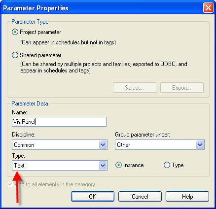
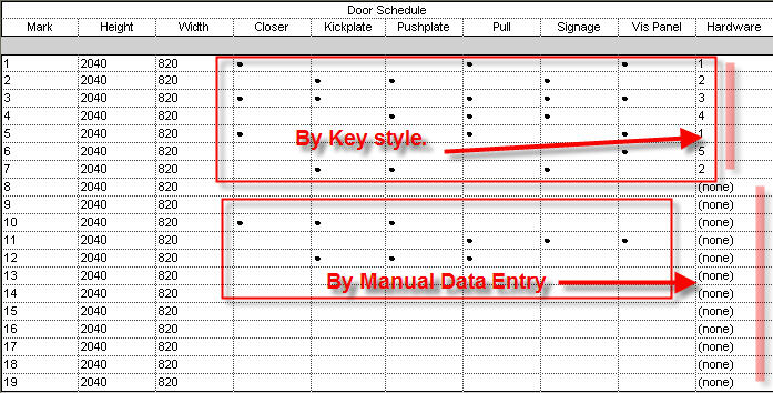
Firstly, create a door schedule by component in the normal way. Add the fields for the different hardware elements. In this case, I'm formating these fields as text fields, so that I can use a matrix for my schedule.


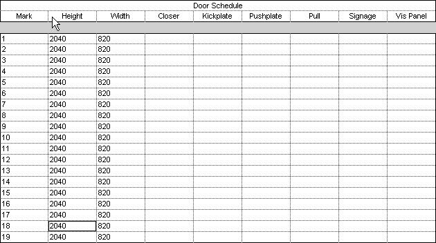
At this stage, the component schedule looks like this.


Now create you key schedule. Note that the Schedule name was changed to Door Hardware Schedule and the key name was changed to hardware.
When you OK this dialogue, the key schedule properties dialogue box appears. It looks exactly like a component schedule, except that the first default field is Key Name .

Select the relevant fields for the different styles that you want to apply to the component schedule. ( I've moved the Key Name field to the bottom of the list. )


When you OK this dialogue, Revit creates the Key Schedule. It looks very unimposing at this point.


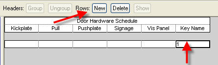
You need to select the Rows > New button in the Options Bar to create a new row. This row will automatically use the key name default number 1. You can change this to any alphanumeric text.
Now you can add symbols to these fields to represent "yes" and leave them blank for "no ".

If you aren't sure how to do this, refer to Steve Stafford's OpEd Blog - Are You A Special Character.

Proceed in this manner to create the styles for you door hardware.

The key schedule now looks like this.


Now return to the Door component Schedule.

Under the Fields tab, a new fields is available - "Hardware ". This is the keyname mentioned earlier.
Add this field to your schedule and use it to populate the rows with the styles applicable to each door.
Note that you can use "none"for the keyname field and enter data manually.
also note that if you use the keyname styles, then you cannot directly modify the fields. In this case, you modify the Key Schedule, by changing the data , this will in turn modify all instances of that style appearing in your component schedule.

A very powerful tool to deal accurately and quickly with a large amount of data !

The completed door schedule looks like this.

( For the final schedule, you would probably hide the Key Name, ie Hardware " column and possibly , use a vertical format for the titles in the hardware columns. )


Monday, December 26, 2005

The Well Tempered Template

One of the key productivity drivers for power users with Revit is the Template file.

This is often an overlooked aspect of the program, since its easy to get excited with the bells and whistles aspects and undervalue the basics.

Revits set up is not difficult. Heres a suggested check list.

Based on one of the default templates, create and save a new template for your company.


Configure file locations: Settings >> Options >> File Locations. Tip __ Remember that you can add icons to your Revit dialogue boxes using the Library file locations.


Set up Units. Settings >> Project Units.


Configure Site Settings. Settings >> Site Settings. ( Contour intervals; Degrees; Poche Base. )
Set Detail Levels for Views.


Configure Line Styles and add any favorites. Delete one you don’t use. Settings >> Line Styles.


Configure Line Patterns and add any favorites. Delete one you don’t use. Settings >> Line Patterns.


Configure Fill Patterns ( Model & Drafting ) – Settings >> Fill Patterns. You may need to build or import your custom patterns.


Configure Materials. – Settings >> Materials.


Configure Object Styles ( Model & Annotation ) – Settings >> Object Styles.


Set up Wall Floor Roof and Ceiling types.


Load Model and Annotation Families. Review the existing families in the template ( if you based it an a default template ) and delete the ones you don’t need.


Configure Phasing. – Settings >> Phases. If you do a lot of renovation work, you could make a separate template , complete with views pre-set to display Existing, Demolished and New work.


Set up your default Levels. ( In elevation views )


Configure View Templates. ( View Templates can be a huge time saver ) View >> Save as View Template & View >> Apply View Templete.


Configure Dimension and Text Styles.


Set up View Tags. Settings >> View Tags.


Create your company titleblock sheets. – File >> New >> Titleblock. Import the titleblock and set up any sheets and sheet numbers that you need as a starter. File >> Load from Library >> Load Family.


On the drawing sheets, load any schedules that you wish to have pre-defined.


Configure Keyboard shortcuts. C:\Program Files\Autodesk Revit Building 8.1\Program\KeyboardShortcuts.txt. ( Print this out for your office reference )


The process of keeping your template file up to date is an important aspect of being really productive. You may have recently made a new material that you would use in many future projects, or a new family, or a new line style etc etc. Review your template regularly and keep it full of the good stuff that will save you lots of time hunting through old projects to find.

Sunday, December 04, 2005

UP ON THE ROOF - PART 2

Last time we were up here on the roof, all our cares just seemed to drift right into space. Suddenly ,we get a reality check - what's wrong with this footprint roof - it's just not generating the roof shape we want or expect !

Well the problem stems from a feature that was introduced in Revit 7 that allowed adjoining sides of a footprint roof to have different eaves heights. A side effect of this new functionality was that roofs may not generate the shape you want.

Here's our floor plan.


FLOOR PLAN.

Nothing particularly special there.

Here's the sketch of the proposed footprint roof.


ROOF FOOTPRINT SKETCH.

And here's the roof generated from that sketch ( in Revit Building 8.1 )


ROOF 3D INCORRECT.

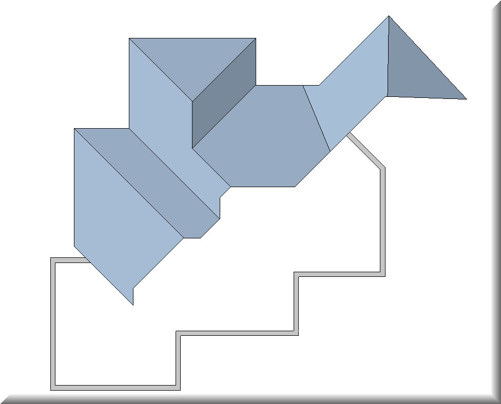
The plan below shows the roof form , with clouds highlighting the junctions which don't conform to our required design.


ROOF PLAN - INCORRECT.

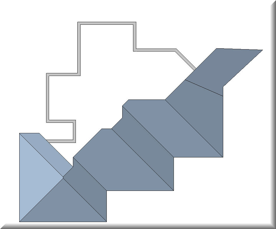
This is what we were hoping to get.


SKETCH OF DESIRED ROOF PLAN.

Using this sketch as a base, we can generate the roof that we want.

First delete the old incorrect roof.

Now we need to analyze the geometry of the proposed roof. Looking at it, it would seem possible to create it as two pieces of roof.

We construct the first piece using pick walls and slope lines and then pick the sketch lines for the valleys, hips and ridges.

The first part of the roof now looks like this.


PART A OF THE PROPOSED ROOF.

Now, we'll make the second part the same way.


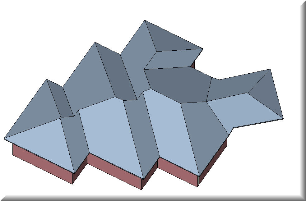
Now we just need to use Join Geometry for the two parts, and here's the roof we wanted.


CORRECT ROOF 3D.

It's taken more effort than a " normal " footprint sketch, but in the end ...

On the roof, it's peaceful as can be

And there the world below can't bother me

Let me tell you now.

Saturday, December 03, 2005

UP ON THE ROOF - PART 1.


On the roof, the only place I know
Where you just have to wish to make it so
Let's go up on the roof (up on the roof)

I really dont know why Revit keeps bringing up these old classics ! First it was Zeplin and now The Drifters are doing it !

In case you havent guessed, were going to be looking at Roofs in Revit.
Revits roofs can be wonderful things - fast and simple to model. They can also be a problem, if you dont know some of the trade secrets.

In this first article, were going to look at how roofs are created, or to be more precise, what rules does Revit apply. In a future article, well look at how to change the shape of a roof that doesnt match the geometry you expected.

One of the simplest and fastest ways to build a roof in Revit is Roof By Footprint.
Using this tool, Revit draws roofs based on the footprint of the outer edge and determines roof planes based on a slope parameter. The footprint sketch must contain a closed loop. Inner loops will define openings. All sounds simple and straightforward doesnt it ? Well, it is, but be aware of the process you use to create your roof.

Lets look at a roof with a 30° pitch drawn and a 500 mm overhang with different options.

Option 1 ( Fig 1 ) Roof drawn using Pick Wall, Truss and Extend to Core not checked.

FIGURE 1.


Option 2 ( Fig 2 ) The same roof, same conditions , except that Extend to Core is selected. Note that the roof overhang is now measured from the core walls outer edge. The pitching point is located at the roof level and the outside face of the core wall.

FIGURE 2.


Option 3 ( Fig 3 ) This time we changed the roof from truss to Rafter and unchecked extend to core. Note that the roof pitching point has moved to the intersection of the roof level with the inside face of the wall.

FIGURE 3.


Option 4 ( Fig 4 ) Same as Option 3, except that Extend to Core has been selected. Note that the overhang is measured from the outer face of the core and the pitching point is on the outer face of the core.


FIGURE 4.


So far we have seen the four possible combinations for constructing a Roof by Footprint using the Pick Wall method. The Pick Wall method is the one I recommend to use most of the time, for two reasons. First, the roof construction is what most users expect, since it uses a wall to define the roof pitching point. Second, if you move the wall in the design, the roof will move with it maintaining the same relationship to the wall. Hips and valleys will remain in place relative to the wall junctions if the walls are moved. If the roof sketch is modified, the hip will remain where it was and the roof eaves height will be changed.
Another thing, the Align eaves tool can be used to adjust the roof setout either by matching eaves heights or eaves overhangs if the roof was sketched by Pick walls.
This Align eaves tool can only use matching eaves heights if the roof was sketched by lines.

Lets have a look now at constructing the same roof using the Lines method.

Option 5 ( Fig 5 ) Same roof, same pitch, sketch using offset 500 mm. Note that you are no longer able to select Rafter or Truss, nor is there a choice for Extend to Core.

FIGURE 5.


The most glaring difference is that the roof is now pitched from its outer edge, not from the wall.

So I hope that now Everything is all right up on the roo-oo-oof ).

Saturday, November 26, 2005

PUT YOUR CITY ON THE REVIT MAP.

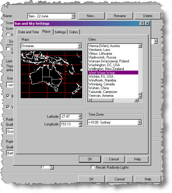
So here you are living and loving life in a small town called West Woop Woop.

You are of course an avid Revit user and youve just been commissioned to design a new high rise office building in the centre of your town. ( Its going to be the first one in fact ! )

You open Revit , knock your design out in next to no time and decide to add some realistic shadows to your presentation.
Youre going to use the Advanced Model Graphics shadow settings By Date Time and Place
Wait a second, what’s going on here... ? you say, ... there are settings for Antananarivio Madagascar, Dohar ( Ad Dawhah ) Qatar and Ulaanbaatar, Mongolia, but none for your beloved Woop Woop. What to do ?

We can help you there. Just move to Sydney!

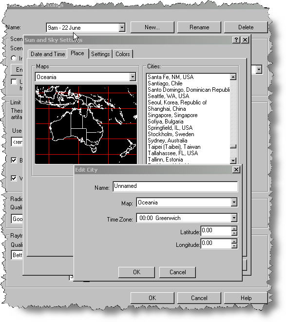
No, sorry, there is another solution. You can Edit the Cities list ( yes, I know ... West Woop Woop isnt really a city,... its more a place you drive through, but bear with me here)


To add a city


1 Open a 3D View..

2 Select Settings, select SUN.

3 Right-click anywhere in the Cities list.


4 From the shortcut menu, click Add.

5 In the Edit City dialog box, enter the name, map, time zone, latitude, and longitude for the city.


To edit a city

4 On the Place tab, right-click on a city in the list, and from the shortcut menu, click Edit.

5 In the Edit City dialog box, enter the name, map, time zone, latitude, and longitude for the city.


To delete a city


4 On the Place tab, right-click on a city in the list, and from the shortcut menu, click Delete.

Of course, we are always saying that there is more than one way to do most things in revit, so for those of you who like to get their hands dirty, here’s another way.

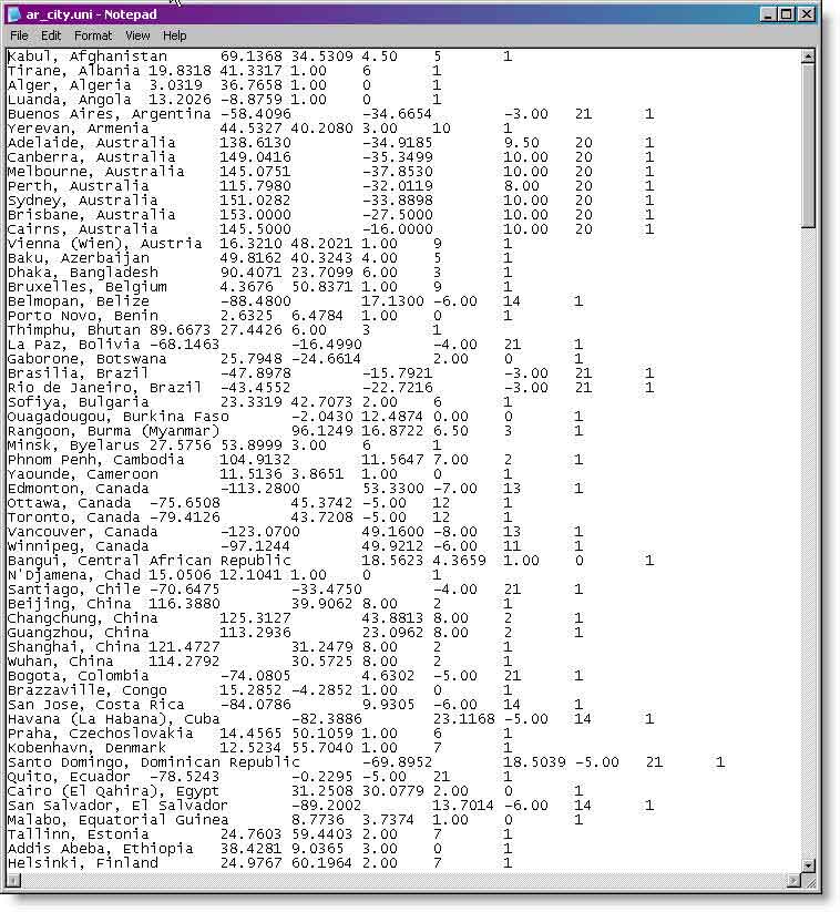
Go to the folder containing your Revit program files and find the folder Ar3Redist\UnicodeENU.

In that folder find the file ar_city.uni . Rename it to something like ar_city.old , so that you have a backup if necessary.

File path example :-C:\Program Files / Autodesk Revit Building 8.1\Program\Ar3Redist\UnicodeENU\Ar_city.uni

The file looks like this.


You can add a row and enter the relevant latitude and longitude and time zone and map reference there if you wish.

So now youre on the Revit map !

Before we finish, I’d just like to send a warm hullo to all our Revit colleagues in Ougadougou, Burkina Faso, who do not have to go this process, because their City is already on the map !

Tuesday, November 22, 2005

ANOTHER WAY OF LOOKING AT IT.

We all know that Revit is a database containing the information required to represent our building design and that each view we take, whether plan, elevation, section or even a schedule is just another way of looking at that data, or part of that data.

Of course, one of the great advantages of a program like Revit is that we can easily and quickly create as many different views as we like and we can show only the information we need in each view. That's a great way to communicate your design intent to any interested parties.

Lets have a look at some of the ways we could do that.

The Section Box:

The first and most common method to help describe aspects of a design would be to use a 3D view. We might refine that by using a 3D view to show just the plan arrangements of different levels.

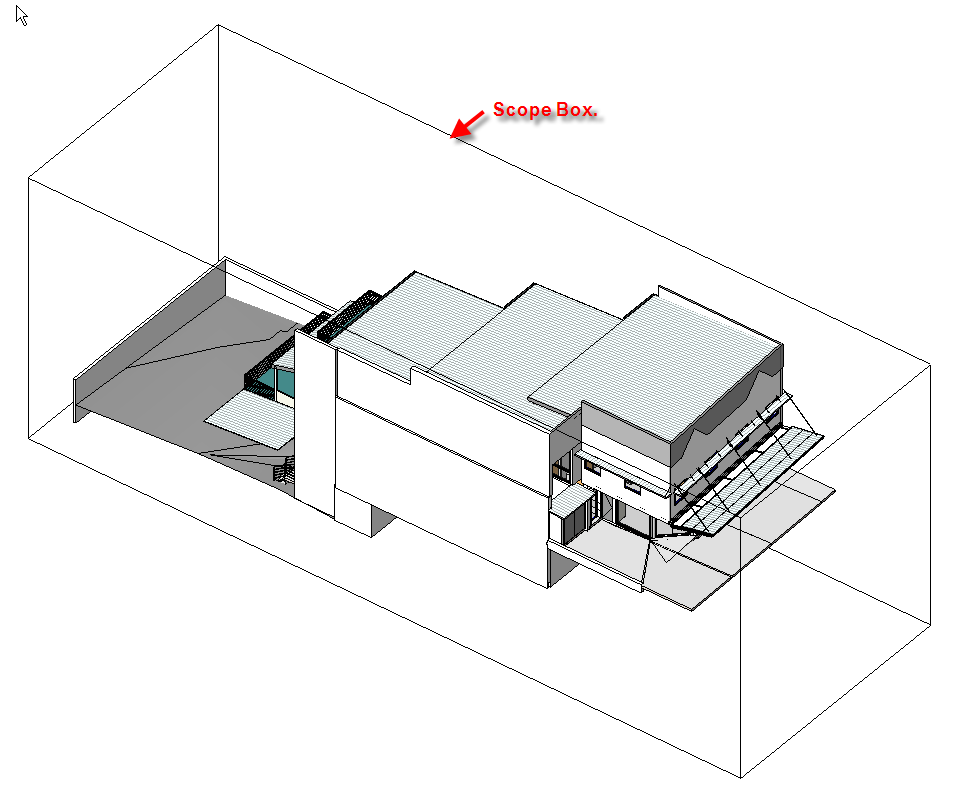
We can do this very easily by using a Section Box.

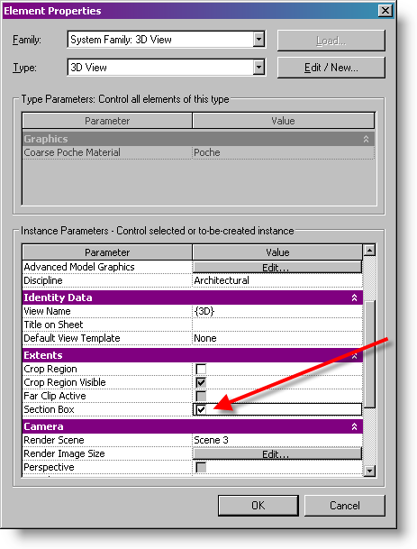
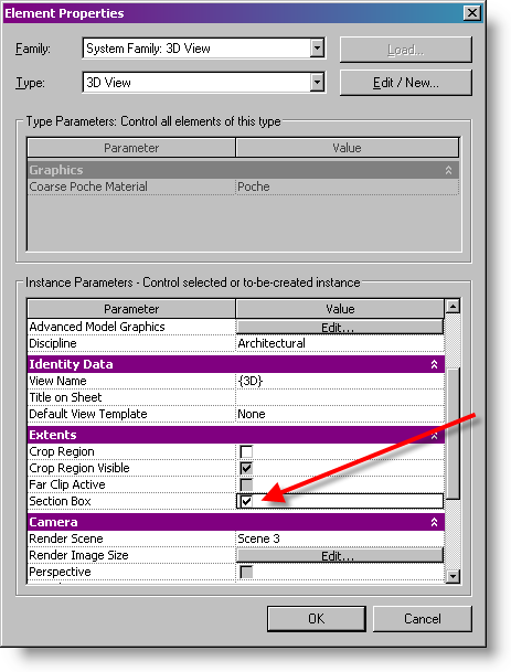
Go to a 3D view of your project. Open the View Properties, Check the box for >Section Box <


A Box appears around your model in a 3D view.


Select the box and blue grips appear. Move the grips to create a cut view of your model. It can take some practice and some fiddling to get them exactly where you want them !
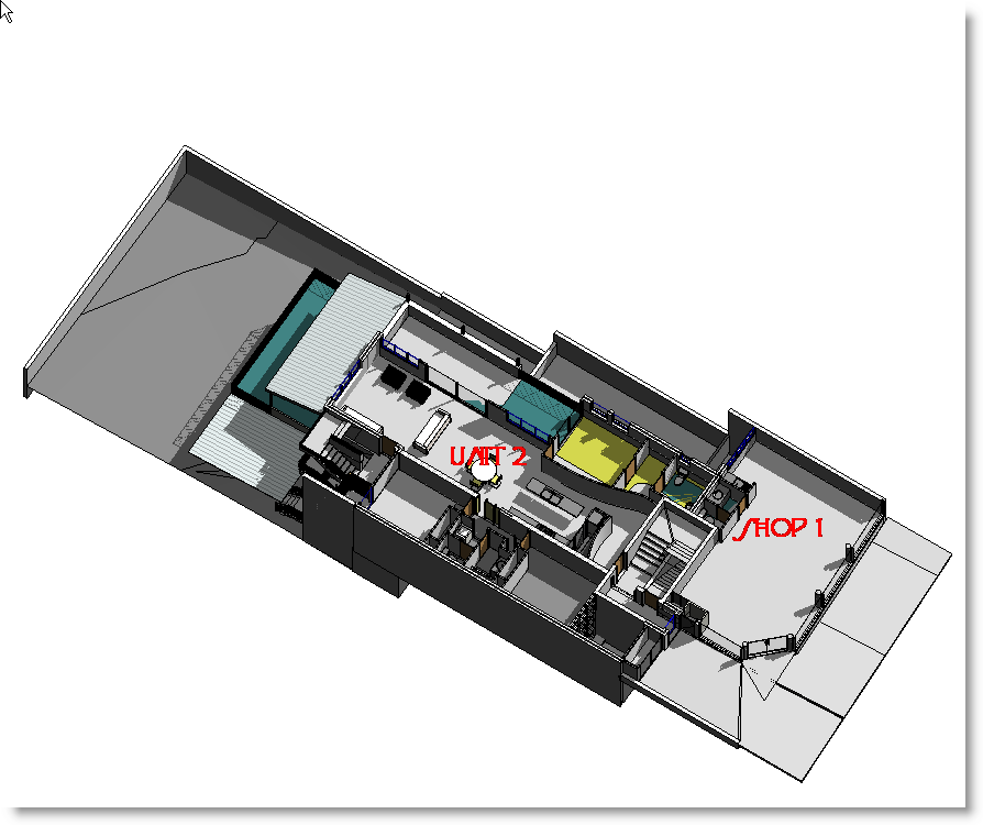
Adjust the orientation and turn on shadows.
Hide the crop region to turn off the section box.
You can add text to help name the areas if you wish.


Save the 3D image.
Turn the section box back on, using the grips, create another view of one of the lower level plans.


Note that you can set the view detail to coarse and then use one of the material definitions > poche <>

Orient to View:

Of course, you've realised by now that there is usually more than one way of doing something in Revit. A view >by section box < is no exception.

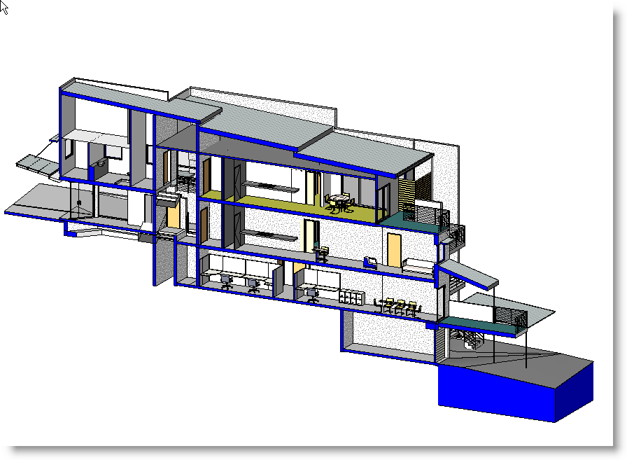
Go to a 3D view. Under the menu tab, View, Orient, select a floor plane view.
It will appear that you are looking at a plan view, but if you spin the image ( using shift and middle mouse button ) you will see its actually a 3D view of the plan.
Cool.


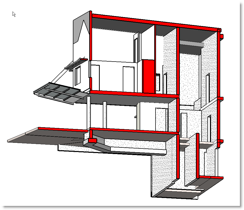
Ah, but it doesn't stop there. Now select a section view to orient to. Viola.


This method can be used to create a 3D detail view also.


And, you can use the power of view templates to setup a view like this to just display the elements you need to see.
For instance, a view template could be used to save the settings to identify only those elements that your engineer may need to see.


Workplane Visibility:

Another handy visualisation tool is a workplane grid.

In a plan view, use the toolbar Tools select Workplane and the workplane visibility. A blue edged rectangle appears in the drawing area.
Select the edges of this rectangle and a grid spacing option appears in the options bar. You can set the spacing for x and y grids, but they must be the same.

Now you can draw elements that snap to those grids. So you could, for instance, draw walls that worked to masonry sizes.


Where this method really comes into itÂ?s own is when you use it for inclined planes.

Draw a reference plane in an elevation or section view.
Using Tools Workplane Set Workplane, select the reference plane by picking it and select a 3D view to work in.

You cannot see the selected plane of course in a 3D view, but you can turn on the workplane grid , as we did before, and now you have a snappable grid to work with and place your beams or whatever.


In future articles we may look at more ways to work with views in Revit.