Sunday, April 30, 2006

Below Stairs

Caller:" Hello, hello, is this the Revit Help Desk " ?

Help Desk: " Yes, how can we help... "

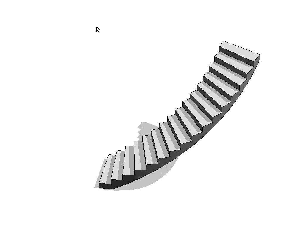
Caller: " Well, I've got this spiral stair and I need to put a wall under it... and I've got to get this project out the door, like yesterday... "


Help Desk: " OK, take a breath, ... Now , firstly you could set up a couple of reference planes each side of the stair, making sure they don't intersect the stair, then name them, then draw detail lines aligned with each stair riser projecting out to each reference plane, then create a new framing elevation using the front named reference plane, checking that the view extents encompass the rear reference plane, then add reference planes where the detail lines intersect both the front and back reference planes ...... "


Caller: "Hey ! I said I need this now ! not next week ! Whadamean create named reference planes and framing elevations ! I can't believe this - there must be a simpler way ! "


Help Desk: ( Calm and patient as always ): " Well yes, but it does involve a work-around... "


Caller: " Great ! I don't care what it involves - just give it to me straight "


Help Desk: " OK, first, select the Ramp tool from the modeling Tab ..."

Caller: " Hey ! I said I wanted a wall, not a *$#@^ Ramp - how long have you been using Revit ? "

Help Desk: ( Calm and patient , but not as calm and patient.. ): " Yes, I know - this is a work around - trust me. Create a new Ramp type and sketch a ramp -like this... same thickness as your wall "


Caller: " Riiight, .... you sure you know what you're doing here... ? "

Help Desk: " Trust me ...., now, from you stair properties, your Actual riser height is ... ? "

Caller: " 177.8 mm "

Help Desk: " And your Actual tread depth is ... "

Caller: " 250 mm "

Help Desk: " OK, so the Ramp Max Slope Type property ( l/x ) should be 250 / 177.8 = 1.4060742. Enter that in the Type Properties, Other... "

Caller: " Hmmmm, OK .... "

Help Desk: " Now measure from the underside of the stair to the upper level - what do you get ? "

Caller: " Ahhh, 550 mm "

Help Desk: " OK, enter that as the Top Offset with a negative dimension "


Help Desk : " Now finish - Click OK " and check out the 3D View "


Caller: " Wow - thanks - you saved me ! Now, how do I put a door in that wall... ? "

Help Desk: " Ahhhh, .... please hold, I have a another call coming in.... "

Tuesday, April 25, 2006

Two Pick , or not...

Revit Building 9 introduces a new family type, known as two pick families.

There are a couple of new family templates provided for creating these families -

  • Generic Model line based.rft
  • Detail Component line based.rft

Both new families contain a reference line with a length dimension attached to it, labeled with the instance parameter length.

Family geometry is built on this reference line and constrained to it.

The resulting family is placed in the same fashion as a wall - by picking two points.

We will proceed to build a Kitchen cabinet family using the Generic Model line based template.

File > New > Family > ( Metric or Imperial ) Generic Model Line Based.rft
We will now construct the carcase for the cabinet.

Add a new Reference Plane and lbel as Carcase Depth - Type parameter.


Soid Form > Solid Extrusion. Sketch the carcase and constrain the sketch to the two side Reference Planes and the rear Reference Line.
Dimension and constrain the carcase thickness ( Keeping it simple for now )


In the front Elevation view, add two new Reference Planes and label them as Bench Height and Plinth Height.
Constrain the carcase to the Plinth Height RP.

Sketch the bench top and the base and constrain to the appropriate Reference Lines.


Add a mid shelf if you wish.

Open a new generic Based family template.

Construct a door panel, with Width and Height parameters ( Thickness can be a parameter or fixed )

Nest this door panel into your 2Pick Cabinet Family.
Constrain to the front RP and to the Left hand ( origin side ) Reference Plane and to the fromt RP.
Set up new parameters as follows :-

Set up a new RP and constrain it to the Panel Width.
Assign the Panel Width and Panel Height parameters to the host families equivalent parameters.
Array the nested door panel, first to last, grouped and constrain the origin to the new RP.

Assign the array number to the parameter " Panel Number "
Go to the front elevation view and constrin the top of the first panel to the Bench Top height.

Flex the family to ensure that everything is working properly.
Add a plinth using a sweep.

Now save, then load the family into a project.
You can now place the cabinet with two picks like a wall.


Cool bananas.

In a future article, we'll look at enhancing the functionality of this family by adding voids to cut the end and the plinth for " L " shaped units, etc.