Sunday, September 10, 2006

A pain in the neck.

One thing that consistently confuses new revit users, appears to be how to rotate a view.

We're not talking about setting Project or True North here. Nor are we talking about rotating a view on a sheet. We're just dealing with the fact that Revit does not have a UCS.

So you have a building orientated at an acute angle to your monitor. What are you going to do ?


Tilting your monitor at an angle might work ?

Turning your head to one side could work ... for a while.... but eventually its going to be a pain in the neck.

You can select the crop region and rotate it.

Trouble is, every time you do that, the building appears to rotate in the opposite direction.

In the example shown, we now that we want the view to be rotated 30 deg clockwise.

If we try to rotate the crop region 30 deg clockwise, this is what we get....

The reason for this is that Revit snaps the crop region back to an X / Y orientation after we have completed the rotation.

So effectively, we get the building maintaining its anglular relationship to the crop boundaries, and therefore appearing to rotate in the opposite direction, when the crop boundaries return to a horizontal / vertical orientation.

Sooo, to get the desired building orientation, we need to rotate the crop region in the exact opposite direction.


Hope that's not too much of a pain in the neck explanation !

Sunday, April 30, 2006

Below Stairs

Caller:" Hello, hello, is this the Revit Help Desk " ?

Help Desk: " Yes, how can we help... "

Caller: " Well, I've got this spiral stair and I need to put a wall under it... and I've got to get this project out the door, like yesterday... "


Help Desk: " OK, take a breath, ... Now , firstly you could set up a couple of reference planes each side of the stair, making sure they don't intersect the stair, then name them, then draw detail lines aligned with each stair riser projecting out to each reference plane, then create a new framing elevation using the front named reference plane, checking that the view extents encompass the rear reference plane, then add reference planes where the detail lines intersect both the front and back reference planes ...... "


Caller: "Hey ! I said I need this now ! not next week ! Whadamean create named reference planes and framing elevations ! I can't believe this - there must be a simpler way ! "


Help Desk: ( Calm and patient as always ): " Well yes, but it does involve a work-around... "


Caller: " Great ! I don't care what it involves - just give it to me straight "


Help Desk: " OK, first, select the Ramp tool from the modeling Tab ..."

Caller: " Hey ! I said I wanted a wall, not a *$#@^ Ramp - how long have you been using Revit ? "

Help Desk: ( Calm and patient , but not as calm and patient.. ): " Yes, I know - this is a work around - trust me. Create a new Ramp type and sketch a ramp -like this... same thickness as your wall "


Caller: " Riiight, .... you sure you know what you're doing here... ? "

Help Desk: " Trust me ...., now, from you stair properties, your Actual riser height is ... ? "

Caller: " 177.8 mm "

Help Desk: " And your Actual tread depth is ... "

Caller: " 250 mm "

Help Desk: " OK, so the Ramp Max Slope Type property ( l/x ) should be 250 / 177.8 = 1.4060742. Enter that in the Type Properties, Other... "

Caller: " Hmmmm, OK .... "

Help Desk: " Now measure from the underside of the stair to the upper level - what do you get ? "

Caller: " Ahhh, 550 mm "

Help Desk: " OK, enter that as the Top Offset with a negative dimension "


Help Desk : " Now finish - Click OK " and check out the 3D View "


Caller: " Wow - thanks - you saved me ! Now, how do I put a door in that wall... ? "

Help Desk: " Ahhhh, .... please hold, I have a another call coming in.... "

Tuesday, April 25, 2006

Two Pick , or not...

Revit Building 9 introduces a new family type, known as two pick families.

There are a couple of new family templates provided for creating these families -

  • Generic Model line based.rft
  • Detail Component line based.rft

Both new families contain a reference line with a length dimension attached to it, labeled with the instance parameter length.

Family geometry is built on this reference line and constrained to it.

The resulting family is placed in the same fashion as a wall - by picking two points.

We will proceed to build a Kitchen cabinet family using the Generic Model line based template.

File > New > Family > ( Metric or Imperial ) Generic Model Line Based.rft
We will now construct the carcase for the cabinet.

Add a new Reference Plane and lbel as Carcase Depth - Type parameter.


Soid Form > Solid Extrusion. Sketch the carcase and constrain the sketch to the two side Reference Planes and the rear Reference Line.
Dimension and constrain the carcase thickness ( Keeping it simple for now )


In the front Elevation view, add two new Reference Planes and label them as Bench Height and Plinth Height.
Constrain the carcase to the Plinth Height RP.

Sketch the bench top and the base and constrain to the appropriate Reference Lines.


Add a mid shelf if you wish.

Open a new generic Based family template.

Construct a door panel, with Width and Height parameters ( Thickness can be a parameter or fixed )

Nest this door panel into your 2Pick Cabinet Family.
Constrain to the front RP and to the Left hand ( origin side ) Reference Plane and to the fromt RP.
Set up new parameters as follows :-

Set up a new RP and constrain it to the Panel Width.
Assign the Panel Width and Panel Height parameters to the host families equivalent parameters.
Array the nested door panel, first to last, grouped and constrain the origin to the new RP.

Assign the array number to the parameter " Panel Number "
Go to the front elevation view and constrin the top of the first panel to the Bench Top height.

Flex the family to ensure that everything is working properly.
Add a plinth using a sweep.

Now save, then load the family into a project.
You can now place the cabinet with two picks like a wall.


Cool bananas.

In a future article, we'll look at enhancing the functionality of this family by adding voids to cut the end and the plinth for " L " shaped units, etc.


Saturday, February 18, 2006

North By Northwest

Hitchcock's 1959 action film North By Northwest, relied on mistaken identity and contained a great deal of extraneous detail to make a simple plot into one of the director's most loved films.

Today, Revit's Project North and True North also create a deal of confusion and mistaken identity among both new and more experienced users.

Lets look at a common scenario in many offices :-

We have a survey dwg from our consultant. We want to use that to create our site boundaries and eventually our topo surface in our Revit file.

The survey drawing is, of course, already orientated to True North.

We import the dwg survey into our project. We import it into the Site Plan view, using Current view and leaving the default orientation set to Project North in the View Properties.


Examining the survey, we determine that the top boundary has a bearing of 82 deg. We want that boundary to be horizontal on our sheet view. Our sheet view will be set to Project North. We will therefore, need to rotate the survey dwg and our property boundaries 8 deg clockwise, to get the correct orientation for Project North.


But first, we need to draw our Revit property lines.

The easy way to do this, is to use Revits query command to identify the layer that contains the boundary line information. Its on layer Boundary_Subject in our case. ( It would be nice if we could isolate it from within the query dialogue, but we can only hide, or delete it )

Under Visibility Graphics, we select the dwg import and turn off all the layers except for Boundary_Subject. We then use the Property line by sketch tool to pick the boundaries. ( remember - hover, tab selects all. )

Turning off our dwg underlay, we can see our Revit property lines. Now we can tag the boundaries using the Tag All Not Tagged feature.


Next, we must rotate the property lines and the dwg to the desired orientation for our sheet views. We do not want to rotate the elevation views tags though.

Turn the dwg back on ( all layers ). Draw a selection box around everything in the Site Plan view, then use the Filter tool to uncheck the Elevation view tags.

Now use the Rotate tool to rotate 8 deg clockwise.


The Site Plan View is now correctly set for Project North ( ie for placing on sheets )

Next, we have to set True North. ( If this is sounding like the plot from an old Hitchcock movie, then I did warn you ! )

It is a relatively straight forward process though.

Rename the Site plan to Site Project North, or similar, so you know which view to use.

Make a duplicate ( with detailing, if you want the dwg visible in this view as well ) of the Site Plan view and rename it Site True North.

Turn off the dwg , for clarity.

Open the View Properties of the duplicated view and change the orientation to True North ( from Project North )

Now, using the Tools menu, Project Position / Orientation, Rotate True North, rotate the project 8 deg anti-clockwise.

You now have a view for each of the desired orientations Project North and True North. The bearings on each property line are correct in both views. The Elevation tags are orientated for the Project North view orientation.

I hope you don't feel like you've just been chased across the face of Mount Rushmore !

But at least now you'll know how to change from North to North West. ( or from Project to True North )

Friday, January 27, 2006

New Revit Blog - In Plain English

Great to see more Revit blogs hitting the net !

The latest one I've seen is Jay Poldings " Revit - In Plain English ".

Check it out.

Thursday, January 05, 2006

Take a Shortcut.

When I'm traveling around the country talking and demonstrating Revit in different organizations, I'm often asked how I instigated a particular task in Revit without using the toolbars.

The answer is Shortcut Keys. ( Revit calls them Keyboard accelerators ).
They have become second nature in my work and I'm sure they will help you to be faster and more productive as well.

You can use the shortcut keys for a wide range of common tasks such as zooming, changing view properties, and adding common elements such as walls.

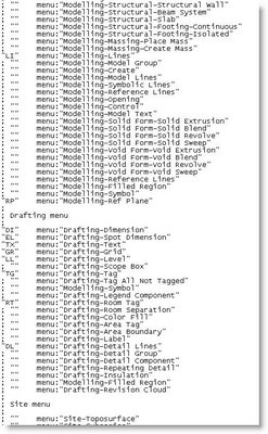
The shortcut file - KeyboardShortcuts.txt is normally found in C:\Program Files\Autodesk Revit Building\Program\. The path may vary depending on your operating system or where you installed Revit Building.

A portion of the file loks like this :-


Out of the box, Revit has about 95 shortcuts pre-defined.

Some of the commonly used shortcut keys are :-

MV Menu Edit > Move

PR Menu Edit > Properties.

DR Menu Edit > Door.

WA Menu Edit > Wall.

WN Menu Edit > Window.

F8 Menu View > Dynamically Modify View.

VV Menu View > Visibility Graphics ( I prefer this to VG, but both work )

VP Menu View > View Properties.

ZF Menu View > Zoom > Zoom to Fit.

ZO Menu View > Zoom > Zoom Out ( 2x ).

ZR Menu View > Zoom Zoom in Region.

SI Snapcode Intersections.

SO Snapcode Snaps Off.

Other useful shortcuts are :-

CTRL ( key ) Selects Multiple elements.

TAB (key ) Cycle through highlighted elements to select those that are close to one another.

TAB (key ) Highlight wall faces or centrelines when placing dimensions.

TAB (key ) Cycle through different snaps while creating walls and lines, placing elements, or moving and pasting elements.

You can customise your own shortcuts for menu commands.

You can create multiple shortcuts for one menu command.

In the menu, the shortcut displayed is the first shortcut listed in the KeyboardShortcuts.txt file. All other shortcuts will work. Shortcuts are only available when their corresponding menu item is available.

Once created, these shortcuts appear next to their corresponding menu item.

Customizing the accelerators requires you to open KeyboardShortcuts.txt.


Locate the file KeyboardShortcuts.txt.

Open the file in a text editor.


At the top of the file you will see several paragraphs with each line preceded by a semi-colon. A list of commands begins after the text. Command lines are not preceded with semi-colons.


Command syntax is as follows:


"key(s)" menu:"menu-string"
Fkey menu:"menu-string
For example, in the following command line, "M" will launch the menu command, Edit, Move.


  • "M" menu:"edit-move"

You can also use F2-F12 keys as keyboard accelerators. These command lines do not surround the shortcut key in quotes. For example, in the following command line, notice that the shortcut key F5 has no quotes. F5 will launch the menu command, View, Refresh.


  • F5 menu:"view-refresh"


Insert a new line between any two existing commands.


Type the new command using the examples above.


Save and close the file.


Restart Revit Building to see the changes.


The file KeyboardShortcuts.log contains any errors encountered while reading this file.
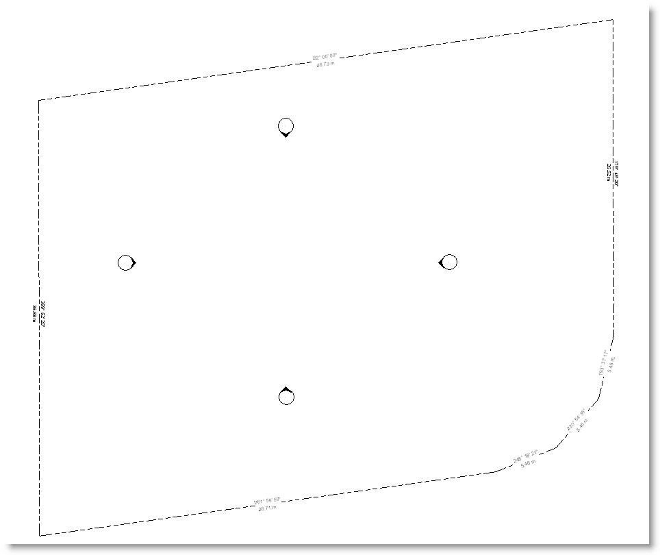


Monday, January 02, 2006

The Key to Schedules.

When you create a schedule in Revit, you will have seen that you can choose "schedule building components "or "schedule keys ".


A key schedule lists styles that you can predefine for use in the schedule; this makes it easy to automatically fill in fields in the schedule, rather than enter them every time by hand.

Say you have a large door schedule, for instance, with many different configurations of hardware. There may be some "hardware types "which apply to many of the doors. This is an ideal situation to use the power of a key schedule.

Firstly, create a door schedule by component in the normal way. Add the fields for the different hardware elements. In this case, I'm formating these fields as text fields, so that I can use a matrix for my schedule.


At this stage, the component schedule looks like this.


Now create you key schedule. Note that the Schedule name was changed to Door Hardware Schedule and the key name was changed to hardware.
When you OK this dialogue, the key schedule properties dialogue box appears. It looks exactly like a component schedule, except that the first default field is Key Name .

Select the relevant fields for the different styles that you want to apply to the component schedule. ( I've moved the Key Name field to the bottom of the list. )


When you OK this dialogue, Revit creates the Key Schedule. It looks very unimposing at this point.


You need to select the Rows > New button in the Options Bar to create a new row. This row will automatically use the key name default number 1. You can change this to any alphanumeric text.
Now you can add symbols to these fields to represent "yes" and leave them blank for "no ".

If you aren't sure how to do this, refer to Steve Stafford's OpEd Blog - Are You A Special Character.

Proceed in this manner to create the styles for you door hardware.

The key schedule now looks like this.


Now return to the Door component Schedule.

Under the Fields tab, a new fields is available - "Hardware ". This is the keyname mentioned earlier.
Add this field to your schedule and use it to populate the rows with the styles applicable to each door.
Note that you can use "none"for the keyname field and enter data manually.
also note that if you use the keyname styles, then you cannot directly modify the fields. In this case, you modify the Key Schedule, by changing the data , this will in turn modify all instances of that style appearing in your component schedule.

A very powerful tool to deal accurately and quickly with a large amount of data !

The completed door schedule looks like this.

( For the final schedule, you would probably hide the Key Name, ie Hardware " column and possibly , use a vertical format for the titles in the hardware columns. )