Saturday, November 26, 2005

PUT YOUR CITY ON THE REVIT MAP.

So here you are living and loving life in a small town called West Woop Woop.

You are of course an avid Revit user and youve just been commissioned to design a new high rise office building in the centre of your town. ( Its going to be the first one in fact ! )

You open Revit , knock your design out in next to no time and decide to add some realistic shadows to your presentation.
Youre going to use the Advanced Model Graphics shadow settings By Date Time and Place
Wait a second, what’s going on here... ? you say, ... there are settings for Antananarivio Madagascar, Dohar ( Ad Dawhah ) Qatar and Ulaanbaatar, Mongolia, but none for your beloved Woop Woop. What to do ?

We can help you there. Just move to Sydney!

No, sorry, there is another solution. You can Edit the Cities list ( yes, I know ... West Woop Woop isnt really a city,... its more a place you drive through, but bear with me here)


To add a city


1 Open a 3D View..

2 Select Settings, select SUN.

3 Right-click anywhere in the Cities list.


4 From the shortcut menu, click Add.

5 In the Edit City dialog box, enter the name, map, time zone, latitude, and longitude for the city.


To edit a city

4 On the Place tab, right-click on a city in the list, and from the shortcut menu, click Edit.

5 In the Edit City dialog box, enter the name, map, time zone, latitude, and longitude for the city.


To delete a city


4 On the Place tab, right-click on a city in the list, and from the shortcut menu, click Delete.

Of course, we are always saying that there is more than one way to do most things in revit, so for those of you who like to get their hands dirty, here’s another way.

Go to the folder containing your Revit program files and find the folder Ar3Redist\UnicodeENU.

In that folder find the file ar_city.uni . Rename it to something like ar_city.old , so that you have a backup if necessary.

File path example :-C:\Program Files / Autodesk Revit Building 8.1\Program\Ar3Redist\UnicodeENU\Ar_city.uni

The file looks like this.


You can add a row and enter the relevant latitude and longitude and time zone and map reference there if you wish.

So now youre on the Revit map !

Before we finish, I’d just like to send a warm hullo to all our Revit colleagues in Ougadougou, Burkina Faso, who do not have to go this process, because their City is already on the map !

Tuesday, November 22, 2005

ANOTHER WAY OF LOOKING AT IT.

We all know that Revit is a database containing the information required to represent our building design and that each view we take, whether plan, elevation, section or even a schedule is just another way of looking at that data, or part of that data.

Of course, one of the great advantages of a program like Revit is that we can easily and quickly create as many different views as we like and we can show only the information we need in each view. That's a great way to communicate your design intent to any interested parties.

Lets have a look at some of the ways we could do that.

The Section Box:

The first and most common method to help describe aspects of a design would be to use a 3D view. We might refine that by using a 3D view to show just the plan arrangements of different levels.

We can do this very easily by using a Section Box.

Go to a 3D view of your project. Open the View Properties, Check the box for >Section Box <


A Box appears around your model in a 3D view.


Select the box and blue grips appear. Move the grips to create a cut view of your model. It can take some practice and some fiddling to get them exactly where you want them !
Adjust the orientation and turn on shadows.
Hide the crop region to turn off the section box.
You can add text to help name the areas if you wish.


Save the 3D image.
Turn the section box back on, using the grips, create another view of one of the lower level plans.


Note that you can set the view detail to coarse and then use one of the material definitions > poche <>

Orient to View:

Of course, you've realised by now that there is usually more than one way of doing something in Revit. A view >by section box < is no exception.

Go to a 3D view. Under the menu tab, View, Orient, select a floor plane view.
It will appear that you are looking at a plan view, but if you spin the image ( using shift and middle mouse button ) you will see its actually a 3D view of the plan.
Cool.


Ah, but it doesn't stop there. Now select a section view to orient to. Viola.


This method can be used to create a 3D detail view also.


And, you can use the power of view templates to setup a view like this to just display the elements you need to see.
For instance, a view template could be used to save the settings to identify only those elements that your engineer may need to see.


Workplane Visibility:

Another handy visualisation tool is a workplane grid.

In a plan view, use the toolbar Tools select Workplane and the workplane visibility. A blue edged rectangle appears in the drawing area.
Select the edges of this rectangle and a grid spacing option appears in the options bar. You can set the spacing for x and y grids, but they must be the same.

Now you can draw elements that snap to those grids. So you could, for instance, draw walls that worked to masonry sizes.


Where this method really comes into itÂ?s own is when you use it for inclined planes.

Draw a reference plane in an elevation or section view.
Using Tools Workplane Set Workplane, select the reference plane by picking it and select a 3D view to work in.

You cannot see the selected plane of course in a 3D view, but you can turn on the workplane grid , as we did before, and now you have a snappable grid to work with and place your beams or whatever.


In future articles we may look at more ways to work with views in Revit.

Monday, November 21, 2005

STAIRWAY TO HEAVEN.


If there's a bustle in your hedgerow don't be alarmed now,
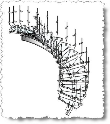
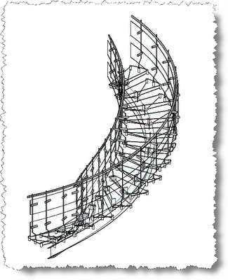
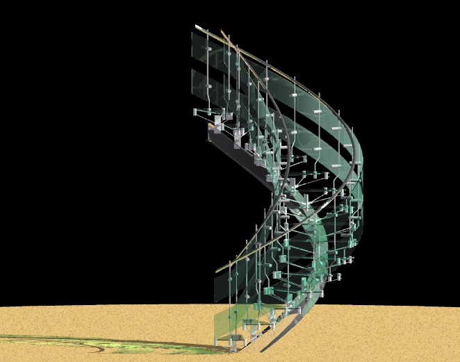
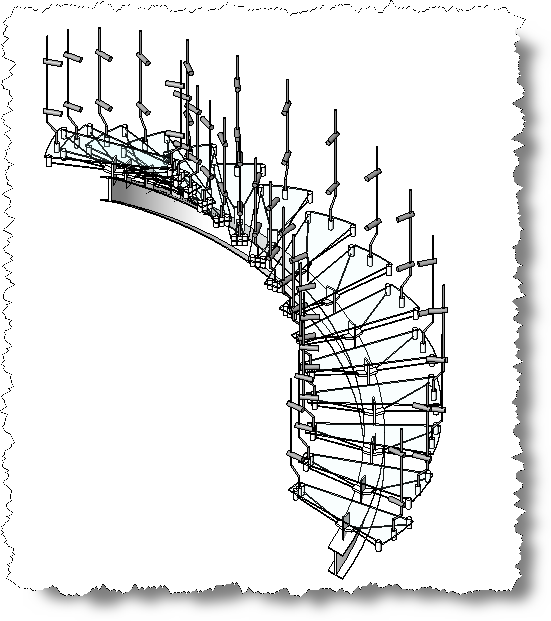
It's just a spring clean for the May queen
.


Oops, sorry, wrong blog ! We're talking here about making customised stairs in Revit.
Something like the one pictured above.

Revit makes stairs very quickly and very easily as we all know, but how do we make a rather more complicated stair like this one ?

You would imagine that we could create a custom profile for the stringer maybe ? Well, no, unfortunately we can’t, but even if we could, it wouldn't help with the special tension members that support the glass treads in this example.

What we need in this case is actually to misuse the railing families.!

Within the Railings Type properties, is a setting to place balusters per tread for a stair. This is the secret to creating a custom stair. The baluster family actually defines the complex geometry of the tread support system system.

Lets run through the process :-

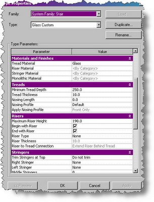
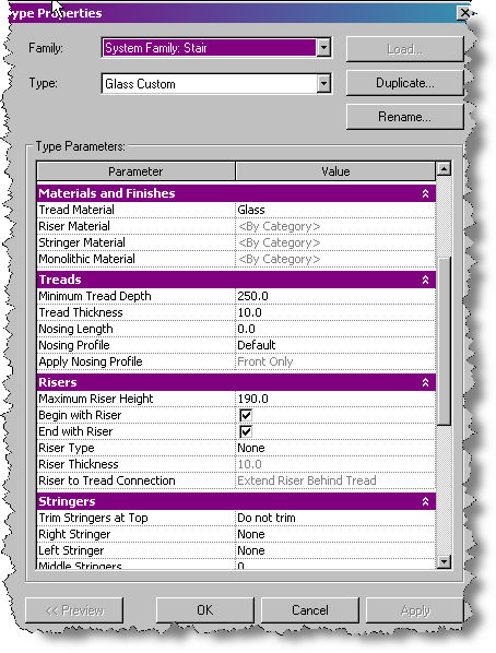
Select the 250 mm going 190 mm riser standard and create a new type called Glass Custom using Edit Duplicate.

Set the width to 1000 mm, In the Type properties, set Tread material to Glass, Tread thickness to 10 mm, Riser Type to none and Right and Left Stringers to none. Then set the Railings to None in the design Bar Sketch Properties.


Draw the stair as an arc with a radius of 1000 mm, Your stair looks something like this.


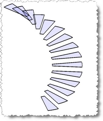
A promising start, but there's higher to climb yet.

Now we need to create the railing family that we will use for the central support stringer and the tension members for the glass treads.
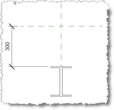
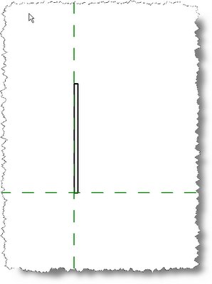
The first step is to create a profile for the central support beam. This is a simple I beam profile set 300 mm below the insertion point. ( 300 mm works - trust me ! )


Next, we make the baluster that consists of a vertical rod with 2 fixing lugs for the side glass panels, We won't spend time describing the process, its just a vertical sweep with 2 horizontal extrusions.


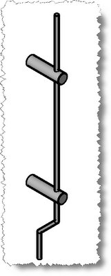
Name the baluster and load it into your library.

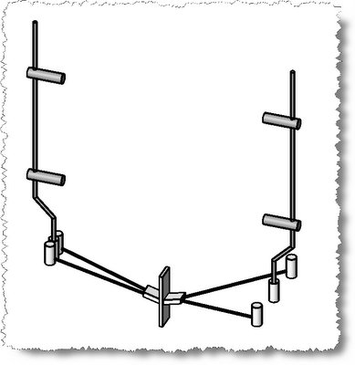
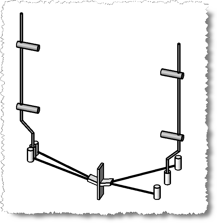
Now, we’re ready to make the Tension Step family. Create an extrusion for the central support plate. Now add a vee shaped extrusion for the 2 tension rods on each side. Model 2 tension rods each side, using a sweep. The geometry of this design can vary to suit your custom design of course. The design isn’t the point of this exercise. Add 6 extruded cylinders – 3 each side, with the outer cylinders connected to the tension rod sweeps. Now import the baluster family and position a baluster at each side on the centre reference plane.

Your Tension Step is complete.


Load the Tension Step into your Stair Project.

In the Stair Project, select Railing from the design Bar tab and then select Railing Properties.. Select the type 900 mm and Edit- Duplicate - Rename to I_Beam. Under the Railing Properties, change the name to I Beam , offset 0 and select the I Beam profile we created in step 6. In the Baluster dialogue, set all baluster families to none for main patter and posts and check the box for placing a baluster at each tread – 1 per tread, selecting the Tension Step as the family for this. Close the railing dialogue.

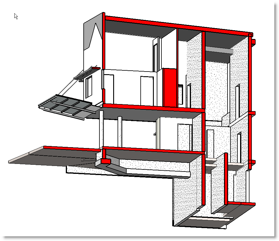
Set the Host as the stair and sketch the railing ( I Beam ) at the centre of the stair.
Finish sketch.


You stair should now look like this. ( Note you may need to use the railing flip arrows to get the correct setup ) Almost there !

And did you know
Your stairway lies on the whispering wind
.


Sorry, got carried away there...


We need some curved glass panels to attach to our balustrades. ( No expense spared for this stair ! )

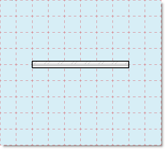
Firstly, we need to make a glass infill panel profile. Open a Profile Family template and create a 300 mm high x 6 mm thick rectangular profile. Save as Glass Infill profile and load this into your project.


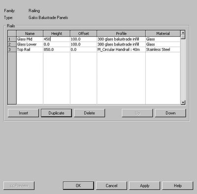
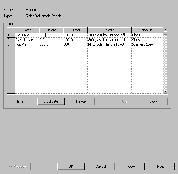
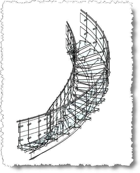
Select the railing tool again and Edit, Duplicate Rename as Glass Balustrade Panels. In the Rail structure properties, make the top rail profile Circular 40 mm diameter Height 850 mm Offset 0 – Material Stainless Steel. Now create a glass panel, Height 0 Offset –100 and profile Glass Infill Panel, Material Glass and set the baluster dialogue to None.. Repeat process for a second glass panel Height 450 mm. ( Tip – Duplicate the railing you just made, rename and change height )


Sketch the railing along the inner edge of your stair. Finish sketch. Check to see that all the locations and offsets are working the way you expect.
Your custom stair is finished.


And as we wind on down the road
Our shadows taller than our soul.
There walks a lady we all know
Who shines white light and wants to show
How ev'rything still turns to gold.
And if you listen very hard
The tune will come to you at last.
When all are one and one is all
To be a rock and not to roll.

All together now - " And we're building a Stairway to Heaven. "

Now, just be careful not to play it backwards.!

Footnote:

The inspiration for this article and the concept for "misusing " the stair railing tool to create the geometry belong to Autodesk Revit's Phi Read ( The Stair Meister ).

Oh and the lyrics belong to Robert Plant.