Of course, one of the great advantages of a program like Revit is that we can easily and quickly create as many different views as we like and we can show only the information we need in each view. That's a great way to communicate your design intent to any interested parties.
Lets have a look at some of the ways we could do that.
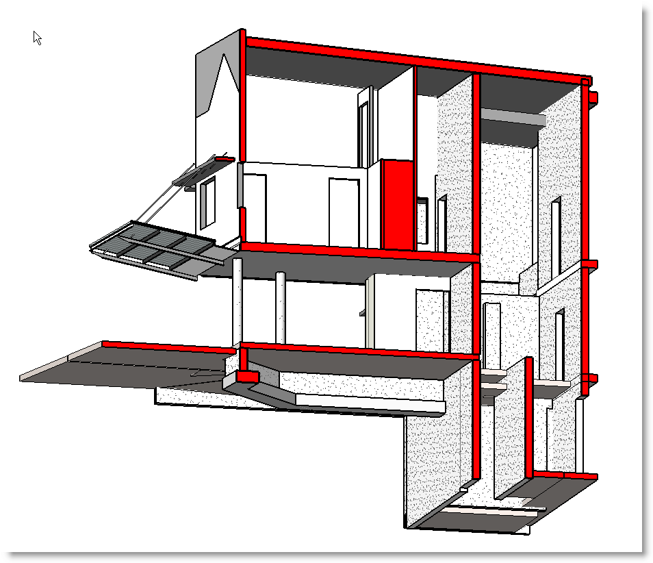
The Section Box:
The first and most common method to help describe aspects of a design would be to use a 3D view. We might refine that by using a 3D view to show just the plan arrangements of different levels.
We can do this very easily by using a Section Box.
Go to a 3D view of your project. Open the View Properties, Check the box for >Section Box <
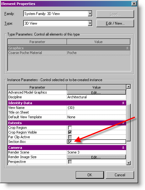
A Box appears around your model in a 3D view.
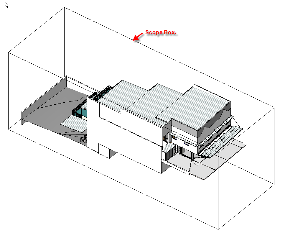
Select the box and blue grips appear. Move the grips to create a cut view of your model. It can take some practice and some fiddling to get them exactly where you want them !
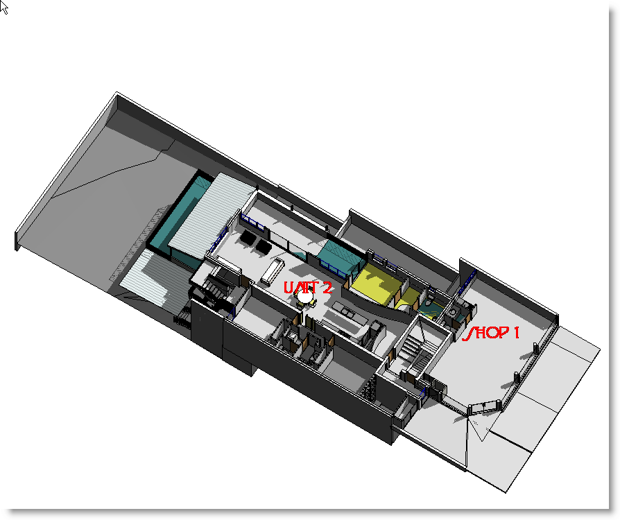
Adjust the orientation and turn on shadows.
Hide the crop region to turn off the section box.
You can add text to help name the areas if you wish.
Save the 3D image.
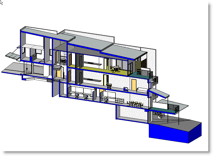
Turn the section box back on, using the grips, create another view of one of the lower level plans.

Note that you can set the view detail to coarse and then use one of the material definitions > poche <>
Orient to View:
Of course, you've realised by now that there is usually more than one way of doing something in Revit. A view >by section box < is no exception.
Go to a 3D view. Under the menu tab, View, Orient, select a floor plane view.
It will appear that you are looking at a plan view, but if you spin the image ( using shift and middle mouse button ) you will see its actually a 3D view of the plan.
Cool.

Ah, but it doesn't stop there. Now select a section view to orient to. Viola.
This method can be used to create a 3D detail view also.

And, you can use the power of view templates to setup a view like this to just display the elements you need to see.
For instance, a view template could be used to save the settings to identify only those elements that your engineer may need to see.
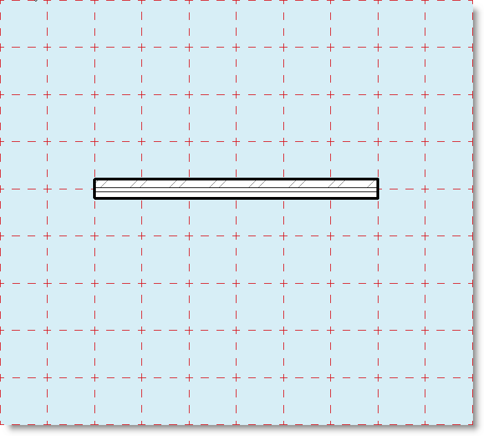
Workplane Visibility:
Another handy visualisation tool is a workplane grid.
In a plan view, use the toolbar Tools select Workplane and the workplane visibility. A blue edged rectangle appears in the drawing area.
Select the edges of this rectangle and a grid spacing option appears in the options bar. You can set the spacing for x and y grids, but they must be the same.
Now you can draw elements that snap to those grids. So you could, for instance, draw walls that worked to masonry sizes.
Where this method really comes into itÂ?s own is when you use it for inclined planes.
Draw a reference plane in an elevation or section view.
Using Tools Workplane Set Workplane, select the reference plane by picking it and select a 3D view to work in.
You cannot see the selected plane of course in a 3D view, but you can turn on the workplane grid , as we did before, and now you have a snappable grid to work with and place your beams or whatever.

In future articles we may look at more ways to work with views in Revit.

1 comment:
Great Blog there BG... keep up the great work!
Post a Comment